State transition testing
State transition testing is used where some aspect of the system can be described in what is called a 'finite state machine'.
This simply means that the system can be in a (finite) number of different states, and the transitions from one state to another are determined by the rules of the 'machine'.
This is the model on which the system and the tests are based. Any system where you get a different output for the same input, depending on what has happened before, is a finite state system. A finite state system is often shown as a state diagram.
If you request to withdraw $100 from a bank ATM, you may be given cash. Later you may make exactly the same request but be refused the money (because your balance is insufficient).
This later refusal is because the state of your bank account has changed from having sufficient funds to cover the withdrawal to having insufficient funds. The transaction that caused your account to change its state was probably the earlier withdrawal.
A state diagram can represent a model from the point of view of the system, the account or the customer.
A state transition model has four basic parts:
- the states that the software may occupy (open/closed or funded/insufficient funds);
- the transitions from one state to another (not all transitions are allowed);
- the events that cause a transition (closing a file or withdrawing money);
- the actions that result from a transition (an error message or being given your cash).
Note that in any given state, one event can cause only one action, but that the same event - from a different state - may cause a different action and a different end state.
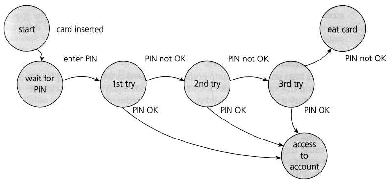
above shown is an example of entering a Personal Identity Number (PIN) to a bank account.
The states are shown as circles, the transitions as lines with arrows and the events as the text near the transitions.
The state diagram shows seven states but only four possible events (Card inserted, Enter PIN, PIN OK and PIN not OK).
There would also be a transition from the 'eat card' state back to the start state.
There would be a 'cancel' option from 'wait for PIN' and from the three tries, which would also go back to the start state and eject the card. The 'access
account' state would be the beginning of another state diagram showing the valid transactions that could now be performed on the account.
However this state diagram, even though it is incomplete, still gives us infor-mation on which to design some useful tests and to explain the state transition technique.
In deriving test cases, we may start with a typical scenario.
- A sensible first test case here would be the normal situation, where the correct PIN is entered the first time.
- A second test would be to enter an incorrect PIN each time, so that the system eats the card.
- We still haven't tested every transition yet. In order to do that, we would want a test where the PIN was incorrect the first time but OK the second time, and another test where the PIN was correct on the third try.
- These tests are probably less important than the first two.
Test conditions can be derived from the state graph in various ways. Each state can be noted as a test condition, as can each transition.
Coverage of all individual transitions is also known as 0-switch coverage, coverage of transition pairs is 1-switch coverage, coverage of transition triples is 2-switch coverage, etc.
Deriving test cases from the state transition model is a black-box approach. Measuring how much you have tested (covered) is getting close to a white-box perspective. However, state transition testing is regarded as a black-box technique.
One of the advantages of the state transition technique is that the model can be as detailed or as abstract as you need it to be.
Where a part of the system is more important a greater depth of detail can be modeled. Where the system is less important , the model can use a single state to signify what would otherwise be a series of different states.
Deriving tests only from a state graph (also known as a state chart) is very good for seeing the valid transitions, but we may not easily see the negative tests, where we try to generate invalid transitions.
In order to see the total number of combinations of states and transitions, both valid and invalid, a state table is useful.
The state table lists all the states down one side of the table and all the events that cause transitions along the top (or vice versa). Each cell then represents a state-event pair.
The content of each cell indicates which state the system will move to, when the corresponding event occurs while in the associated state. This will include possible erroneous events - events that are not expected to happen in certain states. These are negative test conditions.

Table lists the states in the first column and the possible inputs across the top row.
Ex:
- if the system is in State 1, inserting a card will take it to State 2.
- If we are in State 2, and a valid PIN is entered, we go to State 6 to access the account. In State 2 if we enter an invalid PIN, we go to State 3.
We have put a question mark for two cells, where we enter either a valid or invalid PIN when we are accessing the account. Perhaps the system will take our PIN number as the amount of cash to withdraw?
Most of the other invalid cells would be physically impossible in this example.
Invalid (negative) tests will attempt to generate invalid transitions, transitions that shouldn't be possible.
Comments
Post a Comment